logo
Supal (Changzhou) Precision Tools Co.,Ltd
Tentang Kami
Mitra Profesional & andal Anda.
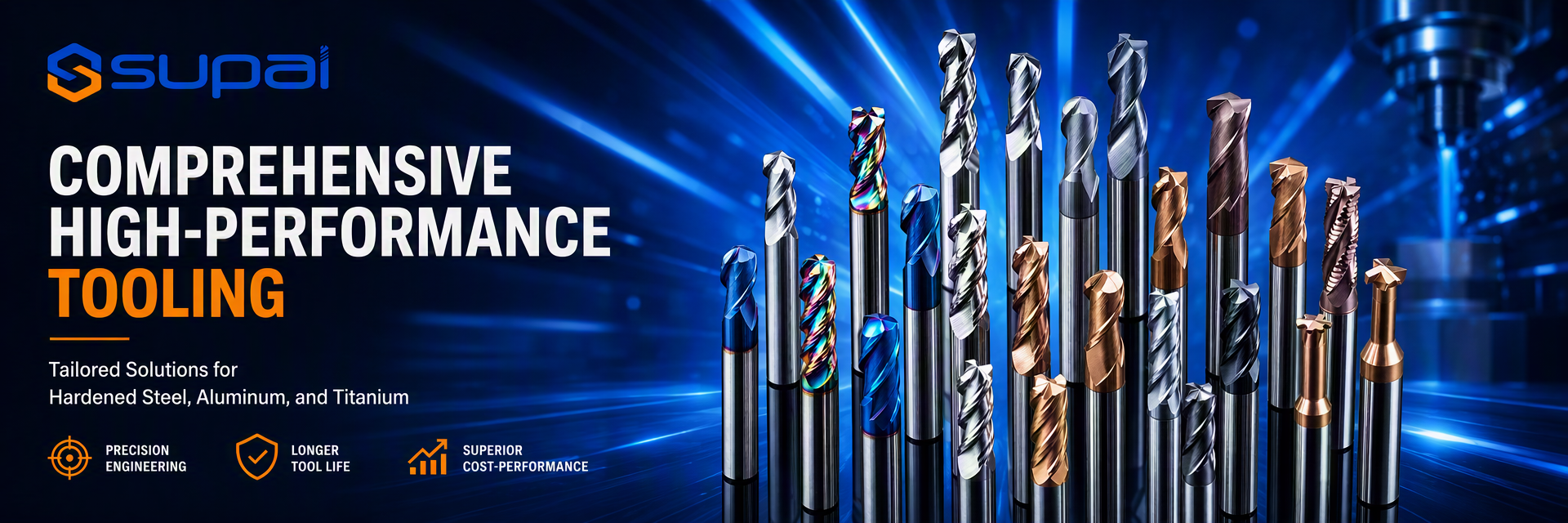
Supal (Changzhou) Precision Tools Co., Ltd. telah terlibat dalam desain, produksi, dan pemasaran alat karbida padat selama bertahun-tahun, dengan total investasi lebih dari 10 juta, dan terdiri dari sekelompok karyawan yang berpengalaman.Sebagai produsen alat profesional, perusahaan ini telah menjadi salah satu anggota direktur Asosiasi Alat Changzhou Xiaxiashu. Perusahaan telah memperkenalkan mesin Walter dan Schutte dari Jerman, ANCA dari Australia, dan mesin penggiling pemotong NC lima sumbu; ...
Pelajari Lebih Lanjut

0

Tahun Didirikan:

0

Juta+
Karyawan

0

Juta+
Penjualan tahunan:
Cina Supal (Changzhou) Precision Tools Co.,Ltd Kualitas Tinggi
Segel kepercayaan, pemeriksaan kredit, RoSH dan penilaian kemampuan pemasok. Perusahaan memiliki sistem kontrol kualitas yang ketat dan laboratorium pengujian profesional.
Cina Supal (Changzhou) Precision Tools Co.,Ltd Pengembangan
Tim desain profesional internal dan bengkel mesin canggih. Kita bisa bekerja sama untuk mengembangkan produk yang Anda butuhkan.
Cina Supal (Changzhou) Precision Tools Co.,Ltd Pengolahan
Mesin otomatis canggih, sistem kontrol proses yang ketat. Kami dapat memproduksi semua terminal listrik di luar permintaan Anda.
Cina Supal (Changzhou) Precision Tools Co.,Ltd 100% pelayanan
Kemasan besar dan kecil yang disesuaikan, FOB, CIF, DDU dan DDP. Biarkan kami membantu Anda menemukan solusi terbaik untuk semua masalah Anda.

Kualitas Alat Penggilingan Karbida & pabrik ujung persegi Pabrikan

Temukan Produk Yang Lebih Baik Memenuhi Kebutuhan Anda.
Kasus & Berita
Titik panas terbaru.
Corner Radius vs Square End Mills for Interrupted Shoulder Milling
Corner Radius vs Square End Mills for Interrupted Shoulder Milling Interrupted shoulder milling is one of the operations where end mill geometry has a direct effect on edge stability. When the cutter repeatedly enters and exits the workpiece, passes across gaps, or encounters uneven stock, each tooth experiences a changing load instead of a smooth continuous cut. A square end mill can produce a sharp 90-degree shoulder, while a corner radius end mill can distribute load around the tool corner and reduce local stress. Choosing between them requires more than looking at the drawing requirement. For CNC machinists, process engineers, and purchasing engineers, the correct decision depends on the balance between required corner definition, interruption severity, tool rigidity, material, engagement, and finishing strategy. This guide compares square and corner-radius geometries for interrupted shoulder milling and explains how to diagnose edge chipping, chatter, poor finish, and unstable tool life. What Makes Interrupted Shoulder Milling Difficult? In a continuous side-milling cut, the cutting edge enters the workpiece and remains engaged in a relatively predictable way. In an interrupted shoulder operation, the edge may encounter a slot, a cross-hole, a casting irregularity, a forged surface, a previous pocket, or an open boundary. Each interruption changes the force and can create impact at entry or exit. The highest-risk conditions usually include: Repeated entry and exit at the same corner of the tool Full radial engagement at a 90-degree shoulder Thin walls or weak workholding that move during the cut Long tool overhang or poor holder runout Abrasive scale, cast skin, or hard inclusions Excessive feed or engagement at the interruption point A sharp square corner exposed to repeated impact A tool can therefore fail even when the average cutting load appears acceptable. The peak impact load, not only the average spindle load, may determine whether the edge survives. Square End Mills: Strengths and Limits A Square End Mill is the natural choice when the part requires a sharp internal shoulder or a flat-bottomed slot. Its geometry can produce a defined 90-degree corner without leaving a programmed radius at the bottom of the wall. When a Square End Mill Is Appropriate Square end mills are often considered when: The finished feature requires a sharp shoulder The toolpath uses stable, continuous engagement The workpiece and fixture are rigid The interruption is limited or can be approached with a controlled entry A separate finishing pass can protect the final corner quality The tool diameter and reach provide sufficient core strength A square tool can perform well in interrupted milling when the edge is properly supported and the engagement is controlled. It should not be rejected simply because the cut is interrupted; the severity and location of the interruption matter. Where Square Corners Become Vulnerable The tool corner is a stress concentration. During an interrupted cut, the corner may take a sudden impact as it enters the material. If the tool is also deflecting, the corner can receive more load than the other flutes. Typical results include corner chipping, a small radius appearing on the part after wear, chatter marks, or an abrupt change in surface finish. A sharp corner can also be sensitive to hard spots, scale, and thin-wall movement. If the failure is concentrated at the corner while the side cutting edges remain relatively intact, geometry and engagement should be reviewed before changing coating alone. Corner Radius End Mills: Strengths and Limits A Corner Radius End Mill includes a controlled radius between the end face and peripheral cutting edge. The radius removes the most fragile sharp corner and distributes cutting load over a larger region of the tool tip. When a Corner Radius Is Advantageous A corner-radius tool is often considered when: The cut includes repeated entry and exit The operation encounters an interrupted or uneven surface Edge chipping is concentrated at a square corner The part drawing permits a small internal radius The operation uses higher engagement or heavier roughing The process needs additional corner strength and more stable tool life The radius does not eliminate vibration or poor setup conditions, but it can reduce the severity of a localized corner impact. It may also improve the tool’s tolerance of intermittent engagement when compared with an otherwise similar sharp-corner tool. The Geometric Trade-Off The main limitation is straightforward: a corner radius leaves a radius on the finished shoulder. If the part requires a sharp 90-degree internal corner, the radius may need to be removed by a secondary operation or replaced by a square finishing tool. A corner radius can also change the effective engagement and contact area. It should be evaluated together with axial depth, radial engagement, tool diameter, and the required surface finish rather than selected based on radius size alone. How to Choose Between the Two Geometries Start With the Drawing Requirement First identify whether a sharp internal corner is functionally required or simply shown as a nominal feature. If a small radius is acceptable, a corner-radius tool may provide a more robust roughing or semi-finishing process. If a sharp corner is essential, use a square tool where practical or plan a roughing-and-finishing sequence that controls the load on the final square edge. Identify the Interruption Type Not all interruptions have the same effect. A predictable open boundary may be easier to manage than a hard casting skin or an irregular forged surface. Cross-holes and slots can create repeated impact at a known location, while uneven stock can make the load unpredictable. Record where the first damage occurs. If chipping starts at every entry point, the issue may be impact or lead-in strategy. If it appears only at a particular section of the workpiece, inspect material condition and support at that location. Match the Tool to the Operation For roughing and semi-finishing, the added corner support of a radius can be valuable when the operation is interrupted. For finishing, a square tool may be preferred if the corner specification requires it and the setup can maintain stable engagement. A practical process may use a corner-radius tool for stock removal, followed by a square end mill for the final shoulder. The two tools should not automatically use identical cutting conditions; the finishing tool may require a different engagement and a more controlled pass. Geometry, Edge Preparation, and Coating Edge Preparation A completely sharp edge may reduce cutting force in some materials, but it can be vulnerable to impact. A lightly reinforced edge may provide better stability in interrupted cuts, although excessive edge honing can increase rubbing and heat. The appropriate edge preparation depends on the workpiece, interruption severity, tool diameter, and operation. When comparing tools, request information about edge preparation rather than evaluating only flute count or coating name. Two tools with similar descriptions may behave differently if their edge preparation and carbide substrate differ. Helix and Flute Configuration Helix and flute count influence force direction, chip evacuation, and the number of teeth sharing the load. A higher flute count may support feed capacity in a light radial finishing pass, while a roughing or interrupted operation may need more chip space and a stronger core. The right balance depends on the material and engagement. A tool with insufficient flute space may recut chips, while a tool with a very thin core may lack impact resistance. Select from the broader Carbide Milling Tools range based on the actual operation rather than relying on the end mill shape alone. Coating Coating should follow the dominant failure mechanism. A coating may help manage heat, adhesion, or abrasive wear, but it cannot compensate for excessive tool deflection, a sharp corner overloaded by impact, or an unstable fixture. If the tool chips at entry, check geometry and rigidity before assuming that a coating change is the primary solution. Any coating recommendation should be validated with the specific material, tool geometry, coolant strategy, and cutting conditions. Treat supplier data as a starting reference and confirm the result on the actual machine. Parameter Strategy for Interrupted Shoulder Milling Cutting data should be treated as a starting reference for the exact diameter, flute count, coating, material grade, tool overhang, and machine setup. Do not transfer a value from a continuous side-milling operation directly to an interrupted shoulder cut without validation. Control the Peak Load at Entry Entry conditions can create the highest impact. Where the geometry allows, use a ramp, arc, or controlled lead-in instead of an abrupt radial plunge. This reduces the sudden change from no load to full engagement. If a direct entry is unavoidable, review feed and radial engagement at the entry point. A controlled reduction in engagement or a separate approach pass may protect the edge better than reducing the entire program feed. Avoid Excessive Full-Width Engagement Full-width shoulder milling creates significant radial load. In an interrupted condition, the load can change sharply as the tool crosses the gap. If possible, use a reduced radial engagement strategy for roughing and leave a controlled allowance for finishing. The correct engagement depends on the tool, material, machine, and feature geometry. Validate changes with spindle load, sound, chip form, and edge inspection rather than assuming that a smaller engagement is always better. Adjust Speed and Feed One Variable at a Time If the tool chips, do not immediately reduce both speed and feed. First determine whether the damage is impact-related, vibration-related, or caused by rubbing. A feed reduction that is too large can create a thin chip and increase rubbing, while a speed change may affect heat and resonance differently. Change one parameter at a time and document the effect. Include the location of the failure, chip appearance, surface finish, and tool condition in the record. Diagnosing Common Failure Symptoms Corner Chipping on a Square End Mill Check interruption severity, tool entry, runout, edge preparation, and whether the square corner is taking the full impact. If the drawing permits it, compare a corner-radius tool in the roughing or semi-finishing stage. If a square corner is mandatory, reduce entry shock and ensure the finishing pass has consistent stock. Chatter on a Corner-Radius Tool A radius does not remove the need for rigidity. Check tool overhang, holder condition, workholding, spindle speed, axial depth, and radial engagement. Chatter may also result from a radius that creates an engagement pattern unsuitable for the current toolpath. Uneven Wear Between Flutes Uneven wear commonly points to runout, unequal flute loading, poor holder seating, or a workpiece that is moving. Inspect the shank, collet, holder, and setup before changing the tool geometry. Poor Shoulder Finish After Roughing A roughing tool with a damaged corner or built-up edge should not be used for a critical finishing pass. Clean the feature, use a sound finishing tool, and verify that the remaining allowance is consistent. If the finish still varies, inspect vibration and workholding. Short Tool Life at a Hard Spot If damage occurs only at a particular location, investigate material condition, scale, interrupted geometry, or inadequate support. A different corner geometry may help, but the toolpath and entry strategy should also be reviewed. Common Mistakes to Avoid Choosing a Square Tool Only Because the Part Has a 90-Degree Corner A square finishing tool may be correct for the final feature but unnecessarily vulnerable during heavy interrupted roughing. Separate stock removal from final corner generation when the process requires both robustness and a sharp corner. Assuming a Corner Radius Always Solves Chipping The radius can improve corner strength, but it does not fix excessive overhang, runout, unstable workholding, poor parameters, or a damaged holder. Reducing Feed Aggressively After Chipping A large feed reduction can cause rubbing and heat. Determine whether the first damage occurred at entry, during an interruption, or under continuous cutting before making broad changes. Ignoring Toolholding The geometry selected on paper cannot compensate for poor holder cleanliness, excessive runout, or unnecessary projection. Check the actual holder and machine setup. Mixing Roughing and Finishing Requirements One tool rarely provides the best combination of high interruption tolerance, high stock-removal capacity, sharp 90-degree finishing, and final surface quality. Define which pass is responsible for each requirement. FAQ Is a corner radius end mill stronger than a square end mill? The radius removes the sharpest corner stress concentration and can improve resistance to local chipping in some interrupted operations. The actual result still depends on material, edge preparation, tool diameter, engagement, rigidity, and parameters. Should I use a corner radius for every interrupted shoulder cut? No. If a sharp 90-degree corner is required, a square end mill may still be necessary for finishing. A corner-radius tool can be considered for roughing or semi-finishing when the part permits a radius or a secondary finishing operation. Why does my square end mill chip only at the entry point? The entry may create an impact or engagement spike. Check lead-in strategy, radial engagement, feed at entry, runout, workpiece support, and the condition of the material surface at the entry location. Can changing the coating stop corner chipping? Only when the dominant failure involves heat, adhesion, or wear that the new coating is suited to control. Coating cannot correct an overloaded corner, poor rigidity, abrupt entry, or excessive engagement. What information should I provide when requesting an end mill recommendation? Provide the material grade, shoulder and interruption geometry, required corner condition, tool diameter and reach, machine and holder details, current parameters, coolant method, tool wear pattern, and photographs of the damaged edge or finished shoulder. Conclusion The choice between a corner-radius and square end mill for interrupted shoulder milling should begin with the part requirement, then consider interruption severity, edge strength, tool rigidity, engagement, and finishing strategy. A square end mill provides a sharp corner but concentrates stress at the tool tip. A corner-radius end mill distributes load more gradually and may reduce local chipping when a radius is acceptable. For demanding operations, a two-stage process can balance both objectives: use a robust geometry for interrupted roughing or semi-finishing, then use a square tool for the final shoulder when the drawing requires a sharp corner. Build parameters from the supplier’s starting range, change one variable at a time, and validate the complete process on the actual machine and workholding. If your shoulder milling process shows corner chipping, chatter, poor finish, or inconsistent tool life, Contact Supal with the material grade, interruption geometry, current tool, tool overhang, parameters, and photos of the failure. This information helps identify a practical geometry and process starting point for on-machine validation.

2026

10/06

How to Choose Carbide End Mills for Copper and Brass Machining
How to Choose Carbide End Mills for Copper and Brass Machining Copper, brass, bronze, and other copper alloys are often described as easy-to-cut materials because they are softer than hardened steel. That description can be misleading. Copper alloys can create very different machining problems depending on their purity, temper, alloying elements, work-hardening behavior, and chip form. A tool that produces a clean result in free-machining brass may rub, smear, or generate built-up edge in a more adhesive copper grade. For CNC machinists, process engineers, and purchasing engineers, reliable copper alloy milling starts with matching the tool to the actual failure mechanism. Edge sharpness, flute space, chip evacuation, workholding, coolant, and parameter validation usually matter more than simply choosing the hardest or most expensive coating. This guide explains how to select carbide end mills for copper and brass machining while reducing adhesion, burrs, heat, and unstable tool life. Why Copper and Brass Need Material-Specific Tool Selection Copper alloys combine several characteristics that influence milling stability: Copper conducts heat efficiently, so heat can move into the workpiece instead of remaining concentrated at the tool edge. However, local rubbing can still raise edge temperature and cause adhesion. Pure or highly ductile copper can produce continuous, gummy chips that are difficult to evacuate. Brass and bronze grades vary widely. Some produce short chips, while others create longer chips or abrasive particles. A dull edge may rub and smear the surface rather than shear it cleanly. Thin walls, small features, and poor workholding can amplify deflection and burr formation. The result is that “copper” or “brass” is not enough information for final tool selection. The exact alloy or grade, hardness or temper condition, feature geometry, and finishing requirement should be confirmed before adopting a production tool. Common Failure Symptoms in Copper Alloy Milling Built-Up Edge and Material Adhesion Built-up edge appears when copper or another ductile alloy adheres to the cutting edge. The tool may look sharp at the beginning of the cut but gradually develops a welded mass that changes the effective edge geometry. This can cause poor surface finish, burrs, dimensional variation, and sudden edge damage when the built-up material breaks away. Adhesion is often promoted by rubbing, insufficient chip evacuation, a dull edge, excessive dwell, or a surface treatment that is not suited to the material. Changing to a harder coating without correcting rubbing may not solve the problem. Smearing and Poor Surface Finish A smeared surface usually indicates that the tool is not shearing the material cleanly. Possible causes include insufficient chip thickness, a dull or heavily honed edge, poor tool runout, unstable workholding, or a speed/feed combination that leaves the tool rubbing instead of cutting. Burrs at Entry and Exit Copper and brass can produce burrs when the cutting edge pushes material away at the exit. Burr formation is influenced by tool sharpness, radial engagement, feed direction, workpiece support, and the condition of the edge. A finishing pass may reduce burrs, but the root cause should still be addressed in the toolpath and tool selection. Chipped Edge or Unexpected Tool Failure Carbide edge chipping in copper alloy milling is not always caused by a material that is too hard. Interrupted cuts, loose workholding, excessive runout, thin-wall deflection, collisions, and trapped chips can generate impact loads that damage the edge. If chipping is concentrated on one flute, inspect runout and setup balance before changing the carbide grade. Chip Packing and Recutting Long copper chips can remain in a pocket, slot, or narrow cavity. Once recut, they create additional heat and load, increasing the chance of built-up edge and surface scratching. Tool geometry and air or coolant direction should be selected with chip travel in mind, especially in deep features. Flute Geometry and Edge Sharpness Choose Enough Chip Space for the Operation Copper and ductile brass grades may require generous flute space so chips can leave the cutting zone before they are recut. A low-flute-count tool can be useful when chip evacuation is the primary limitation, but the correct flute count also depends on rigidity, engagement, feed, finish, and feature geometry. For a deep pocket or slot, prioritize a toolpath and geometry that provide a clear chip path. For a light finishing pass, a different flute configuration may be preferred if it provides the required surface quality without creating excess rubbing. Favor a Clean, Sharp Cutting Edge A sharp edge generally helps shear copper and brass rather than push or smear them. Excessive edge rounding can increase rubbing and heat. However, sharpness must be balanced against the risk of edge damage in interrupted cuts, cast surfaces, abrasive inclusions, or unstable fixtures. The best edge preparation is application-dependent. A stable finishing cut may benefit from a very sharp edge, while a roughing operation with impact risk may require controlled edge reinforcement. Request the intended edge preparation when comparing tools rather than judging only by the product title. Consider Polished Flutes and Rake Surfaces A smooth flute and rake surface can reduce friction and help chips slide away from the cutting edge. This is particularly relevant when the material tends to adhere or when the tool is used in a narrow cavity with limited chip clearance. Polishing alone does not replace the need for suitable flute volume, coolant, or air blast, but it can support cleaner chip transport. Coating and Substrate Considerations Copper alloy applications do not always benefit from the same coating choices used for hardened steel. The dominant issue may be adhesion and friction rather than oxidation or high-temperature wear. In some applications, uncoated polished carbide is appropriate because the sharp, low-friction surface is more important than a hard coating layer. For abrasive copper alloys, bronze grades, or materials containing hard particles, a coating or substrate selected for wear resistance may be useful. The correct choice depends on the exact alloy and failure mode. Do not assume that a coating marketed for hardened steel will automatically improve copper machining, and do not assume that an uncoated tool is correct for every bronze or filled alloy. When comparing copper tools with End Mills for Aluminum, use the aluminum tool as a reference only, not as an automatic substitute. Both material groups can be adhesion-prone, but the exact chip form, edge condition, and surface requirement may differ. Parameter Strategy for Copper and Brass Milling Start With the Actual Tool and Alloy Cutting data should be treated as a starting reference, not a guaranteed setting. The appropriate speed, feed, radial engagement, and axial depth depend on tool diameter, flute count, stickout, machine rigidity, workholding, alloy grade, and coolant or air-blast conditions. Validate the starting range on the actual machine before making it a standard process. Avoid Rubbing and Dwell If the tool spends too much time sliding along the surface, adhesion and smearing become more likely. Check whether the toolpath includes dwell at corners, excessive radial engagement, or a feed value that is too low for the selected edge geometry. A modest, controlled chip load is usually preferable to a cut dominated by rubbing, but the exact value must be validated for the tool and material. Control Chip Evacuation Direct air or coolant so chips move away from the cutting zone rather than being pushed back into the pocket. If chips are long, review flute volume, toolpath engagement, and the conditions that determine chip formation. Increasing fluid pressure without correcting nozzle direction or chip path may produce little improvement. Change One Variable at a Time When troubleshooting built-up edge, burrs, or poor finish, change only one major variable at a time: tool geometry, coating, speed, feed, engagement, or chip evacuation. Document the result. This makes it possible to identify the actual improvement instead of attributing every change to the last tool purchased. Toolholding, Workholding, and Feature Stability Even a well-selected tool can fail when the setup is unstable. Check tool runout, holder cleanliness, clamping length, and the shortest practical tool projection. Thin copper components and unsupported walls can deflect under cutting pressure, leaving burrs or dimensional error that look like a tool problem. For holes and finishing operations, coordinate the milling process with Carbide Drills and Carbide Reamers. A poor pre-hole or unstable entry can reduce the performance of the finishing tool even when the reamer itself is suitable. A Practical Selection and Troubleshooting Sequence Confirm the exact copper, brass, bronze, or copper-alloy grade and condition. Identify the dominant failure: adhesion, burrs, poor finish, chip packing, chipping, or dimensional drift. Select flute count and chip space based on engagement and chip travel, not on flute count alone. Review edge sharpness, rake surface, flute polish, coating, and substrate together. Check runout, overhang, workholding, and thin-wall support. Establish a conservative starting process and validate it on the actual setup. Adjust one variable at a time and record chip form, finish, burr condition, load behavior, and tool wear. Common Mistakes to Avoid Treating All Copper Alloys as Pure Copper Brass, bronze, and specialized copper alloys can produce very different chips and wear mechanisms. A recommendation for one grade should not be transferred automatically to another. Choosing Coating Before Identifying the Failure Mode If adhesion is the primary issue, friction and edge sharpness may deserve attention before thermal coating performance. If abrasion is dominant, the solution may require a different substrate or wear-resistant coating. Diagnose first. Using a Dull Tool for a Finishing Operation A worn edge can rub, smear, and create burrs even when the tool still appears usable. Replace or recondition the tool based on the required surface and dimensional result, not only on visible fracture. Ignoring Chip Travel in Pockets and Slots Long chips that remain in the cavity will be recut. Review toolpath direction, flute space, air blast, coolant placement, and the ability of the machine to clear chips. Copying Parameters From Steel or Aluminum Without Validation Copper alloy behavior is not identical to steel or aluminum. Use supplier data as a starting reference and confirm the process on the actual machine, workholding, and material grade. FAQ What type of carbide end mill is commonly used for copper? A sharp, low-friction tool with suitable chip space is often considered for copper, but the correct flute count, edge preparation, coating, and substrate depend on the exact alloy and operation. Confirm the choice against the material grade and feature geometry. Why does copper create built-up edge on the tool? Built-up edge is commonly associated with adhesion, rubbing, heat concentration, poor chip evacuation, or an edge condition that is not suited to the material. Review sharpness, flute polish, toolpath engagement, and validated parameters before changing coating alone. Is an uncoated carbide end mill suitable for brass and copper alloys? It can be suitable in some applications where a sharp, polished, low-friction edge is the priority. Abrasive bronze or filled copper alloys may require a different wear strategy. The exact recommendation should be confirmed for the specific grade and failure mode. How can I reduce burrs when milling copper? Check tool sharpness, runout, exit engagement, workpiece support, radial engagement, and feed direction. A finishing pass may help, but burr reduction is usually more reliable when the edge and toolpath are stable from the beginning. What information should I provide when requesting a copper alloy tool recommendation? Provide the exact alloy and condition, tool diameter and flute count, feature geometry, tool overhang, machine and holder details, current parameters, coolant or air-blast method, chip form, and photographs of the finish or worn edge. Conclusion Choosing carbide end mills for copper and brass machining requires more than selecting a standard tool for a soft material. The best starting point is to identify the alloy, failure mode, chip behavior, and setup stability. Sharp and suitable geometry, sufficient chip space, controlled friction, reliable evacuation, and validated parameters work together to reduce built-up edge, burrs, smearing, chipping, and inconsistent tool life. If your copper or brass operation has adhesion, burr, chip evacuation, surface-finish, or tool-life problems, Contact Supal with the material grade, feature geometry, current tool, parameters, and failure photos. This information helps evaluate a practical tool and process starting point for on-machine validation.

2026

10/01

Gelembung dan Lubang Terlalu Besar pada Reamer Karbida: Panduan Pemecahan Masalah
Pembicaraan Reamer Karbida dan Lubang Terlalu Besar: Panduan Pemecahan Masalah Reaming sering dianggap sebagai operasi finishing sederhana: bor lubang, jalankan reamer, dan harapkan ukuran dan hasil permukaan membaik. Dalam praktiknya, reaming karbida sensitif terhadap kelonggaran, keselarasan, kekakuan, pengiriman pendingin, geometri tepi, dan stabilitas parameter. Ketika salah satu variabel ini salah, proses dapat menghasilkan tanda-tanda pembicaraan, lubang terlalu besar, kebulatan yang buruk, lubang meruncing, pengelupasan tepi, atau masa pakai alat yang tidak terduga. Bagi operator mesin CNC, insinyur proses, dan insinyur pengadaan, poin kuncinya adalah ini: reamer tidak memperbaiki setiap masalah pengeboran. Reamer dapat memperbaiki lubang yang sudah disiapkan, tetapi tidak dapat secara andal memperbaiki lubang pra-lubang yang sangat tidak sejajar, tergores, terlalu kecil, berbibir lonceng, atau tidak stabil. Panduan ini menjelaskan cara mendiagnosis pembicaraan reamer karbida dan masalah toleransi lubang langkah demi langkah, sehingga tindakan korektif didasarkan pada mode kegagalan daripada tebak-tebakan. Mengapa Masalah Reaming Sulit Didiagnosis Reamer karbida memotong dengan banyak gigi sekaligus dan hanya menghilangkan sedikit material. Karena operasinya ringan dibandingkan dengan pengeboran atau penggilingan, banyak bengkel menganggap reaming seharusnya pemaaf. Kenyataannya, kelonggaran stok yang kecil dan target toleransi yang ketat membuat prosesnya kurang pemaaf. Jika kelonggaran reaming terlalu kecil, alat dapat bergesekan alih-alih memotong. Jika kelonggaran terlalu besar, tepi potong dapat kelebihan beban. Jika lubang yang dibor tidak lurus, reamer dapat mengikuti kesalahan yang ada atau dipaksa untuk memotong secara tidak merata. Jika dudukan atau perlengkapan kurang kaku, getaran kecil dapat muncul sebagai garis pembicaraan yang terlihat di dalam lubang. Inilah sebabnya mengapa reamer yang sama dapat menghasilkan hasil akhir yang sangat baik dalam satu pengaturan dan gagal dalam pengaturan lain dengan diameter lubang nominal yang sama. Gejala Umum dalam Reaming Karbida Tanda Pembicaraan di Dalam Lubang Tanda pembicaraan biasanya muncul sebagai pola spiral berulang atau seperti poligon pada dinding lubang. Mereka menunjukkan bahwa alat, dudukan, benda kerja, atau struktur mesin bergetar selama pemotongan. Pembicaraan dapat disebabkan oleh kelonggaran yang berlebihan, kekakuan yang tidak mencukupi, keselarasan yang buruk, kecepatan yang salah, atau lubang pra-lubang yang tidak stabil. Lubang Terlalu Besar Setelah Reaming Lubang terlalu besar dapat disebabkan oleh runout alat, ketidaksejajaran, tekanan pemotongan yang berlebihan, ekspansi termal, atau chip yang terjebak di antara reamer dan dinding lubang. Jika lubang terlalu besar berulang secara konsisten, ukur runout dan periksa kondisi pra-lubang sebelum menganggap diameter reamer salah. Hasil Permukaan yang Buruk Hasil permukaan yang buruk setelah reaming dapat berasal dari penumpukan tepi, pendingin yang tidak memadai, pemotongan ulang chip, persiapan bor yang buruk, atau tepi potong yang aus. Ketika reamer dipaksa untuk menghilangkan stok yang tidak merata, hasil permukaan seringkali menjadi lebih buruk meskipun alatnya tajam. Masa Pakai Alat yang Pendek atau Tidak Konsisten Jika satu reamer bertahan jauh lebih lama daripada yang lain dalam aplikasi yang sama, tinjau pengaturan mesin, persiapan lubang, pengiriman pendingin, dan variasi material bagian. Pelapisan alat dan tingkatan karbida penting, tetapi ketidakstabilan proses seringkali merupakan hal pertama yang harus dihilangkan. Pengelupasan Tepi Pengelupasan tepi pada reamer karbida sering menunjukkan benturan, pemotongan terputus, kelonggaran yang berlebihan, entri yang buruk, atau inklusi keras dalam benda kerja. Reamer adalah alat finishing; mereka tidak dirancang untuk memperbaiki kesalahan pengeboran besar atau menghilangkan stok berat. Penyebab Akar 1: Kelonggaran Reaming yang Salah Kelonggaran pra-lubang adalah salah satu variabel terpenting dalam reaming. Terlalu sedikit stok dapat menyebabkan gesekan, panas, dan hasil akhir yang buruk. Terlalu banyak stok dapat membebani tepi potong dan menyebabkan pembicaraan atau pengelupasan. Tidak ada kelonggaran universal yang cocok untuk setiap diameter, material, dan desain reamer. Sebagai prinsip awal, lubang berdiameter kecil umumnya membutuhkan kelonggaran yang lebih kecil, sementara lubang yang lebih besar dapat mentolerir lebih banyak penghilangan stok. Namun, nilai yang benar tergantung pada material benda kerja, kedalaman lubang, geometri alat, metode pendingin, dan target toleransi. Selalu validasi kelonggaran pada mesin dan perlengkapan aktual daripada menyalin nilai dari operasi lain. Saat memecahkan masalah, bandingkan diameter lubang bor aktual sebelum reaming dengan target akhir. Jika ukuran pra-lubang bervariasi dari satu bagian ke bagian lain, hasil reaming juga akan bervariasi. Penyebab Akar 2: Kualitas Pra-Lubang yang Buruk Reamer membutuhkan panduan yang stabil. Jika lubang yang dibor sudah tidak pada posisinya, meruncing, tergores, atau sangat mengeras karena kerja, reaming menjadi jauh lebih sulit. Sebelum menyalahkan reamer, periksa proses pengeboran. Periksa apakah bor menghasilkan lubang yang bulat dan lurus, apakah chip menggores dinding, dan apakah bor bergeser saat masuk. Untuk kontrol proses pembuatan lubang, Bor Karbida dan reamer harus dipilih sebagai sistem, bukan sebagai alat yang tidak berhubungan. Jika bor meninggalkan goresan chip yang parah atau ukuran lubang yang tidak konsisten, reamer mungkin tidak memiliki kontrol yang cukup untuk memperbaiki cacat tersebut. Tingkatkan stabilitas pengeboran terlebih dahulu, lalu evaluasi lintasan reaming. Penyebab Akar 3: Runout dan Ketidaksejajaran Runout adalah salah satu cara tercepat untuk menghasilkan lubang terlalu besar dan keausan alat yang tidak merata. Sedikit runout pada dudukan atau spindel dapat membuat satu tepi potong bekerja lebih keras daripada yang lain. Ini menciptakan tekanan pemotongan yang tidak merata, kebulatan yang buruk, dan masa pakai alat yang lebih pendek. Periksa runout pada tangkai alat dan di dekat bagian pemotongan jika memungkinkan. Tinjau juga kondisi dudukan, kebersihan collet, kondisi spindel, dan apakah alat dijepit dengan panjang kontak yang cukup. Untuk lubang presisi, sistem penahan alat sama pentingnya dengan reamer itu sendiri. Ketidaksejajaran juga dapat terjadi ketika reamer memasuki lubang yang tidak koaksial dengan jalur spindel. Ini umum terjadi ketika operasi sebelumnya, perlengkapan, atau pengaturan jangkauan panjang menimbulkan defleksi. Penyebab Akar 4: Kecepatan, Umpan, dan Stabilitas Pemotongan Parameter reaming harus cukup stabil untuk memotong dengan bersih tanpa gesekan atau getaran. Kecepatan yang terlalu tinggi dapat meningkatkan panas dan memperburuk pembicaraan pada beberapa material. Umpan yang terlalu rendah dapat menyebabkan gesekan alih-alih memotong. Umpan yang terlalu tinggi dapat membebani tepi dan merusak hasil permukaan. Untuk pemecahan masalah, sesuaikan satu variabel pada satu waktu. Jika muncul pembicaraan, mengurangi kecepatan sedikit dapat membantu, tetapi hanya jika kekakuan dan kelonggaran sudah masuk akal. Jika alat bergesekan dan menghasilkan panas, meningkatkan umpan dalam kisaran yang aman terkadang dapat meningkatkan aksi pemotongan. Perubahan parameter harus divalidasi melalui pemotongan percobaan pada material bagian aktual. Hindari menggunakan tabel kecepatan dan umpan generik sebagai nilai akhir. Perlakukan mereka sebagai referensi awal dan sesuaikan berdasarkan ukuran lubang, kedalaman, kekakuan mesin, pendingin, dan persyaratan toleransi. Penyebab Akar 5: Kontrol Pendingin dan Chip Meskipun reaming menghilangkan lebih sedikit material daripada pengeboran, chip tetap penting. Chip halus atau partikel yang terjebak di dalam lubang dapat menggores dinding dan merusak tepi potong. Pendingin membantu membersihkan chip, mengurangi panas, dan menstabilkan zona pemotongan. Untuk lubang buta, evakuasi chip menjadi lebih sulit karena chip memiliki ruang terbatas untuk keluar dari dasar lubang. Arah, tekanan, dan aliran pendingin harus ditinjau dengan cermat. Jika chip tetap berada di lubang dari pengeboran, bersihkan atau bilas lubang sebelum reaming. Konsentrasi dan filtrasi pendingin juga penting. Pendingin yang terkontaminasi dapat membawa partikel abrasif kembali ke dalam lubang, memengaruhi hasil permukaan dan masa pakai alat. Penyebab Akar 6: Geometri Reamer dan Kesesuaian Aplikasi Berbeda Reamer Karbida dirancang untuk aplikasi yang berbeda. Faktor-faktor seperti desain alur, sudut utama, desain margin, persiapan tepi, dan pelapisan dapat memengaruhi stabilitas pemotongan dan evakuasi chip. Reamer untuk lubang tembus mungkin tidak berperilaku sama di lubang buta. Reamer yang dioptimalkan untuk aluminium mungkin tidak ideal untuk baja tahan karat atau material yang dikeraskan. Reamer panjang mungkin memerlukan perhatian ekstra pada kekakuan dan runout. Saat membahas masalah reamer dengan pemasok, berikan material benda kerja, diameter pra-lubang, target toleransi, kedalaman lubang, kondisi lubang tembus atau lubang buta, metode pendingin, parameter saat ini, dan foto permukaan lubang jika tersedia. Informasi ini membantu menentukan apakah solusinya adalah perubahan geometri, perubahan parameter, atau koreksi proses. Alur Kerja Pemecahan Masalah Praktis Langkah 1: Ukur Pra-Lubang Sebelum memeriksa lubang jadi, ukur lubang yang dibor atau dibor sebelum reaming. Catat diameter, kebulatan, kelurusan jika memungkinkan, dan kondisi permukaan. Jika pra-lubang tidak stabil, perbaiki terlebih dahulu. Langkah 2: Periksa Runout Alat Ukur runout pada dudukan aktual. Bersihkan tangkai, collet, dan dudukan. Ganti dudukan yang rusak atau collet yang aus. Jika runout berkurang dan lubang terlalu besar membaik, reamer bukanlah penyebab utama. Langkah 3: Tinjau Kelonggaran Bandingkan diameter pra-lubang aktual dengan ukuran reamer. Jika kelonggaran bervariasi antar bagian, identifikasi mengapa operasi pengeboran atau pembubutan tidak konsisten. Langkah 4: Periksa Chip dan Hasil Permukaan Cari chip yang terjebak di lubang, goresan, atau tanda gesekan. Jika muncul goresan chip, tingkatkan aliran pendingin dan pembersihan pra-lubang. Langkah 5: Sesuaikan Parameter Secara Bertahap Ubah kecepatan, umpan, atau pendingin satu faktor pada satu waktu. Catat hasilnya. Hindari mengubah geometri alat dan parameter secara bersamaan kecuali pengaturan saat ini jelas tidak sesuai. Langkah 6: Tinjau Pemilihan Alat Jika proses stabil tetapi masalah tetap ada, tinjau geometri reamer, pelapisan, gaya alur, dan persiapan tepi. Untuk operasi pemesinan dan finishing terkait, Supal juga menyediakan Alat Penggilingan Karbida untuk perencanaan proses CNC yang lebih luas. Kesalahan Umum yang Harus Dihindari Kesalahan 1: Mengharapkan Reamer Memperbaiki Lubang yang Buruk Reamer adalah alat finishing, bukan alat penyelamat. Jika lubang yang dibor sangat tidak terpusat, meruncing, atau tergores, perbaiki pra-lubang terlebih dahulu. Kesalahan 2: Mengabaikan Runout Runout dapat membuat reamer yang akurat memotong terlalu besar. Selalu ukur alat pada dudukan aktual alih-alih menganggap alat itu sendiri salah. Kesalahan 3: Menggunakan Kelonggaran Terlalu Sedikit Terlalu sedikit material dapat menyebabkan gesekan, panas, dan hasil akhir yang buruk. Alat harus memotong, bukan memoles stok yang tidak beraturan. Kesalahan 4: Menggunakan Kelonggaran Terlalu Banyak Terlalu banyak material dapat membebani tepi potong dan menyebabkan pembicaraan, pengelupasan, atau kebulatan yang buruk. Kesalahan 5: Mengubah Diameter Reamer Sebelum Memeriksa Proses Jika lubang terlalu besar karena runout, ketidaksejajaran, atau pembicaraan, mengubah diameter alat mungkin tidak menyelesaikan masalah akar. FAQ Mengapa reamer karbida saya menghasilkan lubang terlalu besar? Penyebab umum termasuk runout, ketidaksejajaran, kelonggaran yang berlebihan, kualitas pra-lubang yang tidak stabil, chip yang terjebak, atau efek termal. Ukur runout dan ukuran pra-lubang sebelum menganggap diameter reamer salah. Bisakah reamer memperbaiki penyimpangan bor? Hanya sampai batas tertentu. Jika lubang yang dibor sangat tidak pada posisinya atau tidak lurus, reamer dapat mengikuti kesalahan yang ada. Tingkatkan proses pengeboran atau pembubutan terlebih dahulu. Apa yang menyebabkan pembicaraan selama reaming? Pembicaraan dapat disebabkan oleh kelonggaran yang berlebihan, kekakuan yang buruk, kecepatan yang salah, overhang alat yang panjang, geometri pra-lubang yang tidak stabil, atau keselarasan yang buruk antara spindel dan lubang. Haruskah saya mengurangi kecepatan atau umpan untuk menghentikan pembicaraan reamer? Terkadang mengurangi kecepatan membantu, tetapi itu tidak selalu solusi pertama. Periksa runout, kelonggaran, kekakuan dudukan, dan kualitas pra-lubang terlebih dahulu. Umpan yang terlalu rendah juga dapat menyebabkan gesekan. Informasi apa yang harus saya kirim saat meminta dukungan pemecahan masalah reamer? Kirim material benda kerja, diameter pra-lubang, diameter target dan toleransi, kedalaman lubang, kondisi lubang tembus atau lubang buta, metode pendingin, kecepatan/umpan saat ini, overhang alat, jenis dudukan, dan foto permukaan lubang atau reamer yang aus. Kesimpulan Pembicaraan reamer karbida, lubang terlalu besar, dan masa pakai alat yang pendek biasanya adalah masalah proses, bukan hanya masalah alat. Urutan pemecahan masalah yang paling efektif adalah mengukur pra-lubang, memeriksa runout, meninjau kelonggaran, memeriksa tanda permukaan, dan menyesuaikan parameter satu variabel pada satu waktu. Jika Anda menghadapi toleransi lubang yang tidak stabil, tanda pembicaraan, atau masa pakai reamer yang pendek, Hubungi Supal dengan material benda kerja Anda, kondisi pra-lubang, target toleransi, parameter saat ini, dan foto kegagalan. Supal dapat membantu mengevaluasi apakah akar penyebabnya adalah kelonggaran, runout, pendingin, geometri reamer, atau stabilitas proses secara keseluruhan.

2026

09/29